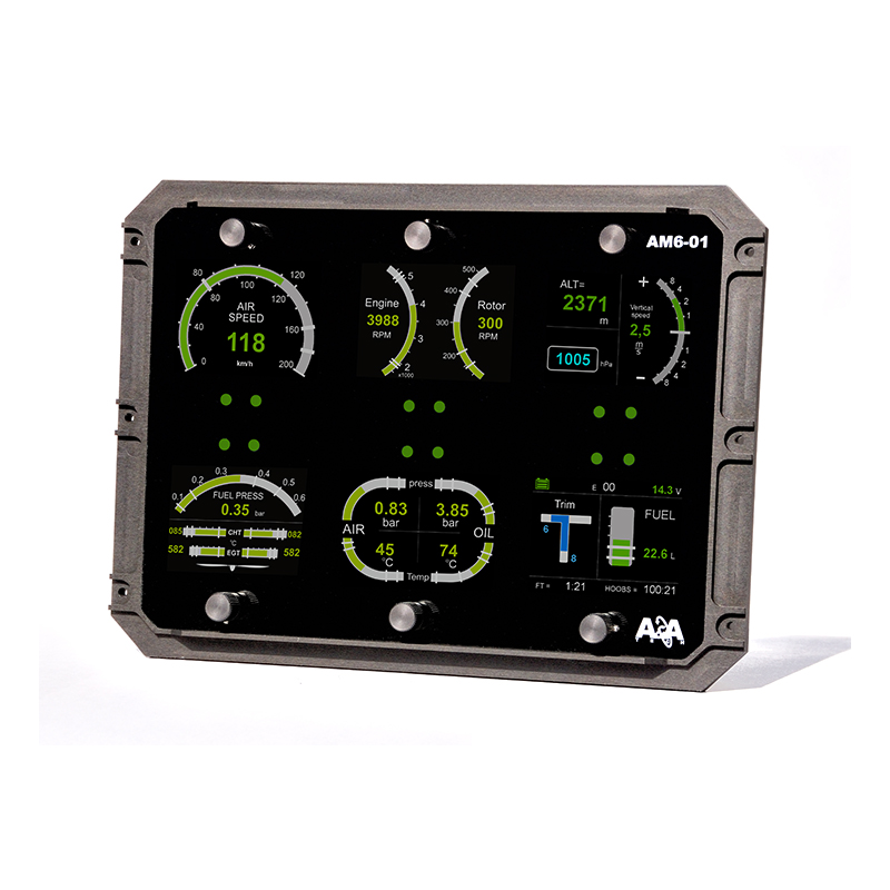
Display type EEM AM6 01 GR03
This instrument presents flight and engine parameters.
The instruments include four displays. They presents parameters:
1. Display A (upper left) type FL01.01:
- Air speed of the aircraft
2. Display B (upper middle) type FE01.06:
- Engine speed;
- Rotor speed;
3. Display C (upper right) type FL02.01:
- Altitude – in the upper left quarter of the display;
- Vertical speed – on the right side of the display;
- Reference pressure – in the bottom left quarter of the display;
4. Display D (bottom left) FE04.02:
- Fuel pressure – in the upper side of the display;
- Cylinder head temperature – in the middle of the display; its right bar graph shows the temperature of the right side of the cylinder head, and the left bar graph – the temperature on the left of cylinder head;
- Exhaust gas temperature – in the bottom of the display; its right bar graph shows the temperature measured of the right side of the engine, and the left bar graph – the temperature on the left;
5. Display E (bottom middle) type FE02.02:
- Inlet air pressure – in the upper left quarter of the display;
- Inlet air temperature – in the bottom left quarter of the display;
- Oil pressure – in the upper right quarter of the display;
- Oil temperature – in the bottom right quarter of the display;
6. Display F (bottom right) type FE03.02:
- Pitch trim position – vertical bar graph on the left side of the display;
- Roll trim position – horizontal bar graph in the upper left quarter of the display;
- Fule level – bar graph on the right;
- Flight time (measured from the last start of the engine) – digits in the bottom left of the display;
- Hobbs (total engine running time) – digits in the bottom right of the display;
- Voltage – the upper left of the display;
- Number of recorded threshold crossings – the upper centre of the display (e00).
|
Lp. |
Parameter |
Symbol/ name in display |
Unit |
Range of bar graph indicator |
Warning/alarm thresholds |
|
|
Warning |
Alarm |
|||||
|
1 |
Air speed of the aircraft |
AIR SPEED |
km/h
|
0 200 km/h |
under 60 km/h
from 160 to 180 km/h |
above 180 km/h |
|
2 |
Altitude |
ALT |
m, ft |
--- |
--- |
--- |
|
3 |
Variometr |
Vertical speed |
m/s, ft/min |
± 8 m/s |
--- |
--- |
|
4 |
Reference pressure |
--- |
hPa, mmHg, inHg |
---- |
--- |
--- |
|
5 |
Engine speed |
ENGINE |
RPM |
0 – 6000 rpm |
from 1400 to 1600 rpm#
from 5500 to 5800 rpm |
under 1400 rpm#
above 5800 rpm |
|
6 |
Rotor speed |
ROTOR |
RPM |
0 – 600 |
from 150 |
under |
|
|
|
|
|
rpm |
to 200 rpm#
from 400 to 450 rpm |
150 rpm#
above 450 rpm |
|
7 |
Inlet air pressure |
MAP |
bar |
0 – 1,5 bar |
from 1,4 to 1,45 bar |
above 1,45 bar |
|
8 |
Inlet air temperature |
MAT |
°C, F |
from -5 to 70°C |
from 0 to 5°C
from 50 to 60°C |
under 0°C
above 60°C |
|
9 |
Oil pressure |
OIL p |
Bar |
0 – 7,5 bar |
from 1,0 to 2,5 bar#
from 5,0 to 7,0 bar |
under 1,0 bar#
above 7 bar |
|
10 |
Oil temperature |
OIL T |
°C |
0 – 140 °C |
from 50 to 60°C
from 110 to 130°C |
under 50°C
above 130°C |
|
11 |
Cylinder head temperature |
CHT |
°C |
0 – 120°C |
from 100 to 110°C |
above 110°C |
|
12 |
Exhaust gas temperature |
EGT |
°C |
0 – 900°C |
under 500°C #
from 850 to 900°C |
above 900°C |
|
13 |
Voltage in electric power instalation |
--- |
V |
---- |
from 11 to 12V
from 14 to 15V |
under 11V
above 15V |
|
14 |
Fuel level |
FUEL |
L |
0 70 l |
------- |
-------- |
|
15 |
Fuel pressure |
FUEL |
bar |
0 0,6 |
from 0,1 to 0,15 bar
from 0,4 to 0,5 bar |
under 0,1 bar
above 0,5 bar |
|
16 |
Flight time |
FT |
H:min |
---- |
------- |
-------- |
|
17 |
Total engine running time |
HOOBS |
H:min |
---- |
------- |
-------- |
|
17 |
Number of recorded threshold crossings |
E |
--- |
---- |
----- |
----- |
|
18 |
Trim pitch |
TRIM |
- |
|
------- |
-------- |
|
19 |
Trim roll |
TRIM |
- |
|
------- |
-------- |
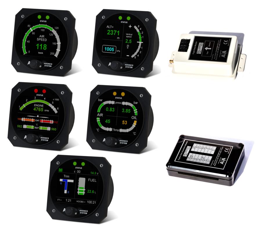
The casing is made of anodised aluminium. The LCD display is protected by high quality acrylic cover with anti-glare coating. This makes the device durable and easy to maintain.
The readings are displayed in both digital and graphical form. For immediate recognition of the status, colour codes are used. If the air speed stays within the desired range, the instrument displays values in green. If the warning threshold is crossed, the instrument informs the pilot by changing the colour of graphs and digits to orange. If alarm levels are reached, the digits and graph bars turn red. The threshold values (both upper and lower) are to be defined by the buyer at placing an order.
| Parameter | Value | |
| Dimensions (height x width x depth) | 248 x 183 x 55 mm | |
| Display diameter | 156 x 164 mm | |
| Mass | 585 g | |
| Power supply | 12 V (< 510mA) | |
For details see the manual.
-
 Flight Data System FLS/helicopters/planes/ultralight autogyros/ultralight fixed-wing aircraftsAdd to cart
FLS AM1 01
1 193,10 € -
 Integrated Avionics System IAS/ultralight fixed-wing aircraftsAdd to cart
IAS AM1 AR01
1 950,00 € -
 Engine Data System EDS/ultralight autogyrosAdd to cart
EDS AM1 GR01
1 228,77 € -
 Engine Data System EDS/ultralight autogyrosAdd to cart
EDS AM1 GR02
1 228,77 €